I'm builing a droid. This is my progress so far...
Drive Train
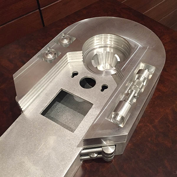
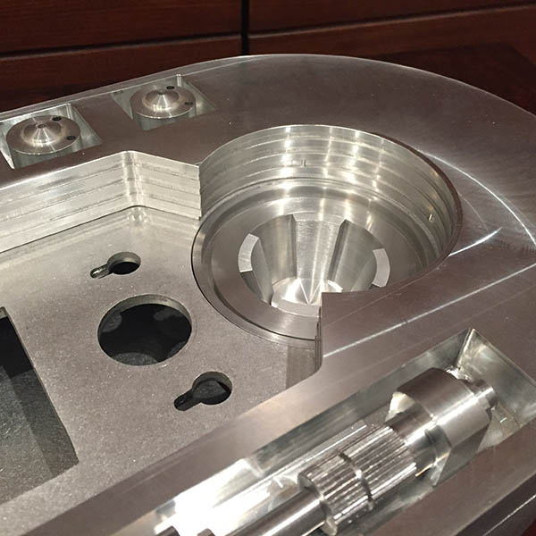
So I've been talking a lot to a builder in Sweden through my sister's-husband's-sister's-friend (whoa). And as we were on the topic of drive trains he helped me make complete sense of the Senna Drive Train. Thank you Serdar. While there are some good pictures of people building these drive trains there aren't a lot of good drawings and close ups so I drew it up in Solidworks and the whole setup makes a lot of sense to me now. I've ordered all my parts for the drive train and it should be delivered pretty soon. In the meantime here's a breakdown of the drive train.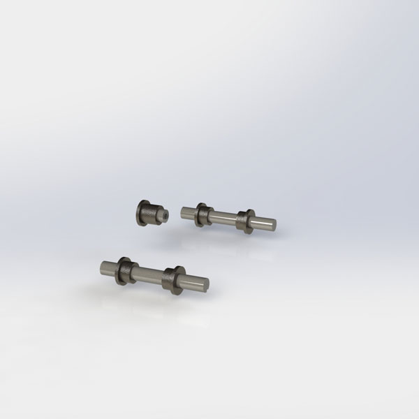
Two 1/2" shafts for the wheels with bushings in the 3/4" holes.
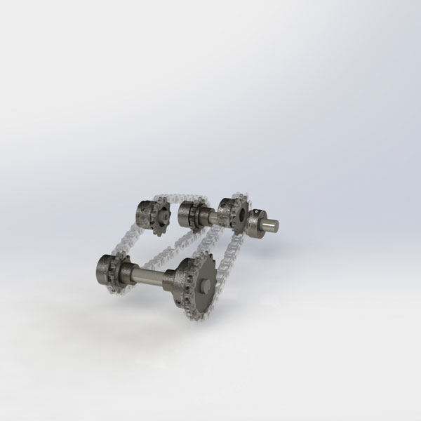
Sprockets are attached to the shafts and the chain tension is controlled by the center sprocket.
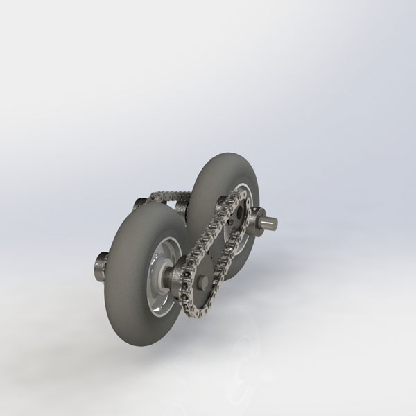
Note that this isn't the assembly order - just images to help you understand the mechanism.
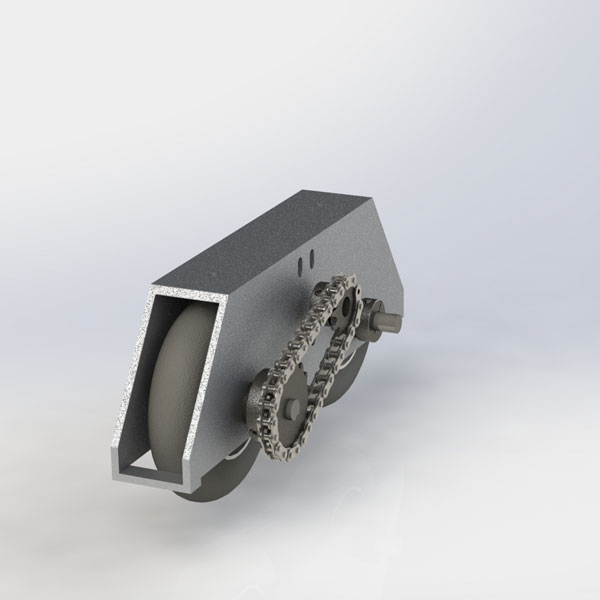
The housing is a rectangular aluminum profile that has been cut. I'll post drawings later but they are dimensionally the same as Mike Senna's drawings.
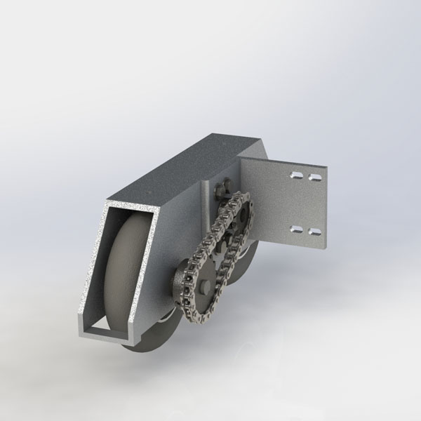
L bracket mounted for the motor.
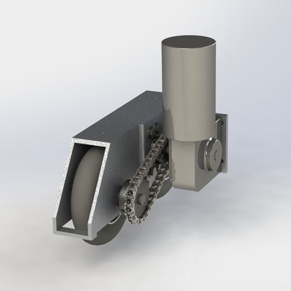
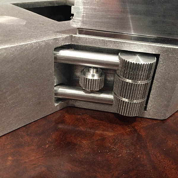
Full assembly
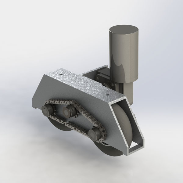
And from the other side. Also note that there is no slack in the chains in these renderings. There should be.
Assembly
My screw collection has grown even bigger. It's amazing how many different types of screws you collect when building an R2. I try to stick to a few standard sizes like 2-56 for skins or 4-40 for most of the frame parts. Then of course 1/4-20 for everything structural in the frame and the occasional 10-32. Some parts attach with 6-32 but sometimes you suddenly have metric. Like the leg parts use M5 and some other odd parts have M4.
Anyway, I've been working on putting together my new frame. I learned a lot with putting the old CS:L frame together and figuring out where the best location for everything was. My new frame is CS:R and I went ahead and redesigned it a bit. For this version of the droid I'm keeping the ring design since the skins I have is front/back.
I've assembled most of the frame. The only thing missing is three horizonal rails for the utility arm carriage. Drilling curved pieces is a pain in the butt but I guess I should just suck it up and do it already.
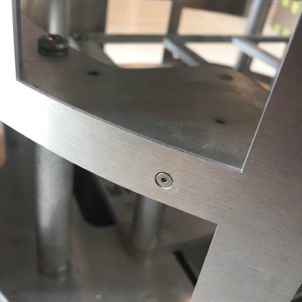
Hinged Rear Door
The mechanism is pretty simple. I made an offset hole in the top and middle rings so that the radius would be a little bit bigger and clear the rear skin when opened.
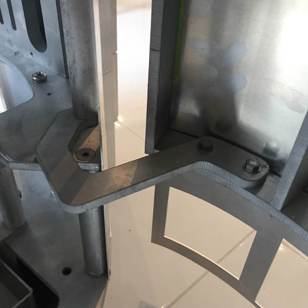
Attached with 10-32 bolts at the bottom and 10-32 countersunk flat head screws at the top.
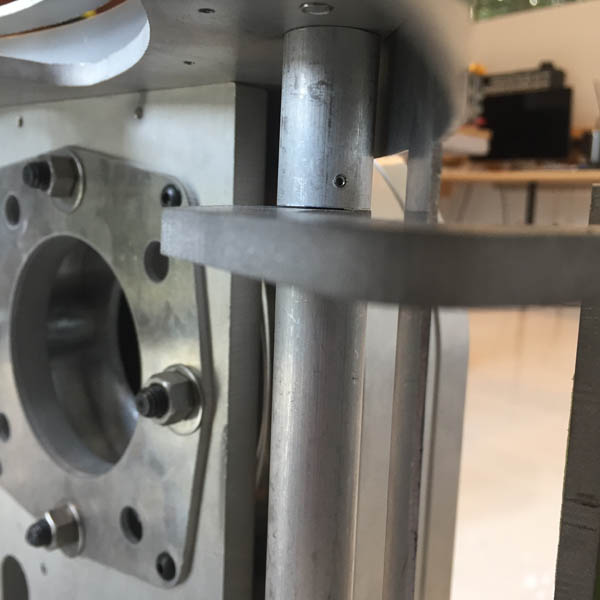
The rod has a 1/4" pin in the center and a small bushing pressed into the arm pivot helps the door open and close smoothly. The pin is secured with a small 4-40x1/4" set screw (Not that it's going anywhere but I figure I put a set screw in there for good measure).
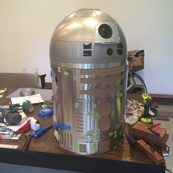
Skins
All the inner skins are mounted. I used custom skin blocks that are attached to the top ring, the middle ring and the shoulder plates. The main screws that holds the skins are 4-40 flat heads and then I put a few 2-56 screws in various places where the skins needed a tighter fit.
Still a tiny gap on once side but maybe I can tighten it later.
Legs
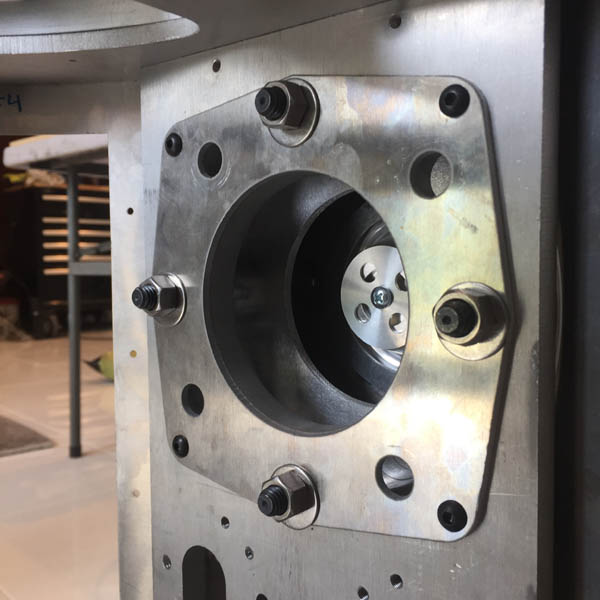
The legs are mounted with 1/2"x2" shoulder screws. I had to put a 7/16" washer inside the leg because the length of the thread on the shoulder screw.
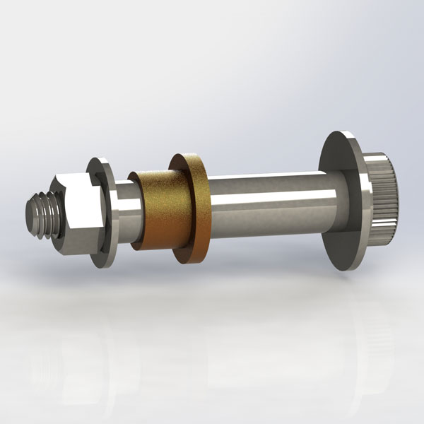
Here's the shoulder screw with washers, flanged bushing and nut.
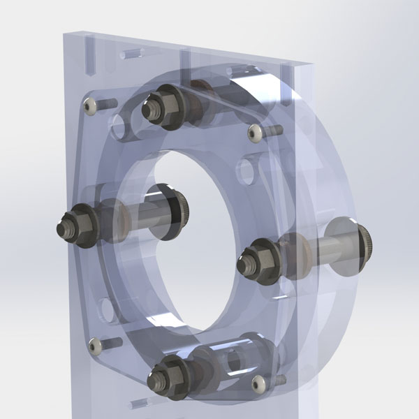
And here's the assembly.
Other
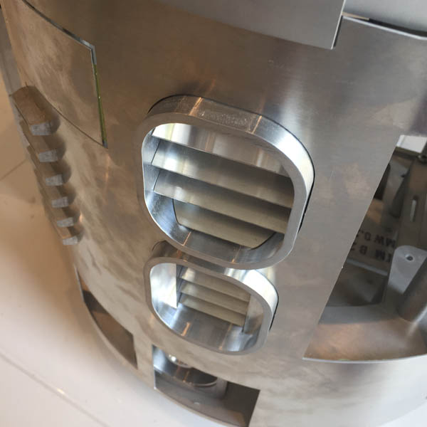
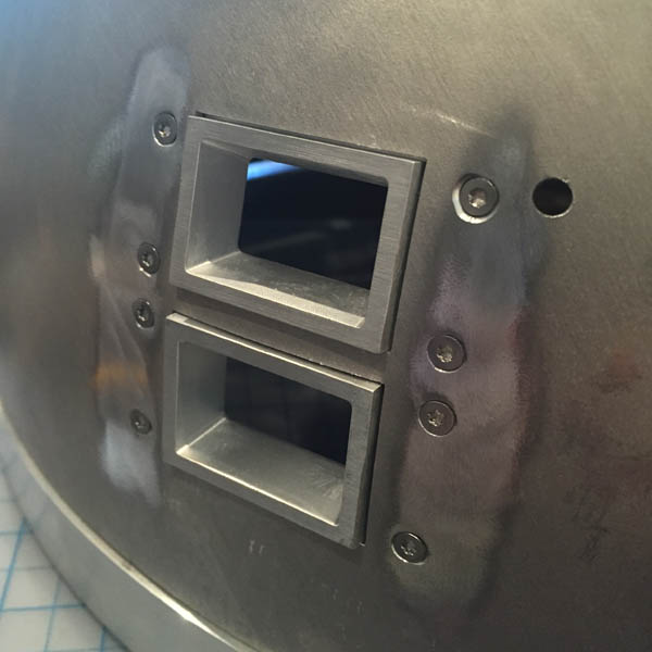
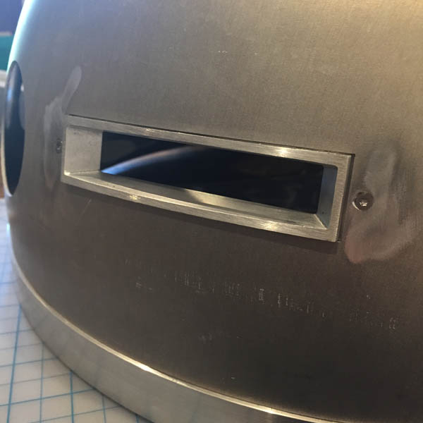
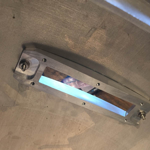
My front vents came a couple of weeks ago and I could finally mount them. They're pretty much already fixed in position because of the tight fit between the rails and the front skin. But I put some set screws to fixate them just in case. The vents are from Wayne and they are absolutely beautiful.
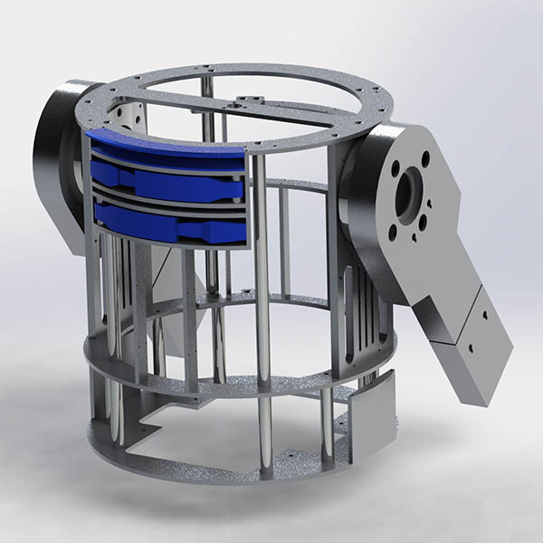
CSR Frame
When I initially set out to build the droid I was working from the CSL blueprints. After a while I decided to go entirely CSR (because of accuracy and part availabilty) so I knew that the time would come when I would need to change the frame to CSR too. So far I've been able to test out a lot of things with my CSL frame but now that I'm starting to get closer to mounting legs and so on, I really need to upgrade the frame. I could have just bought a frame kit from one of the part runs but I feel I've learned so much from working it out on my own. And that was the goal from the start - to learn as much as possible about the manufacturing and machining process. And amass an impressive collection of screws of course.
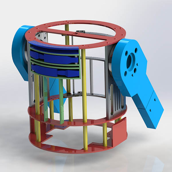
So I've worked out mostly all the issues with the new frame. I'm not entirely done yet. A major difference between the two frames is of course the larger diameter. I also wanted to build a hinged door on the back of the droid so that I can install Li-ion batteries on the back part instead of on top of the skirt. I haven't decided if I'm going to change design of the middle ring yet to support a future 2-3-2 conversion but it might be appropriate. I'll probably still go with the same Shoulder Mounting Plates as before.
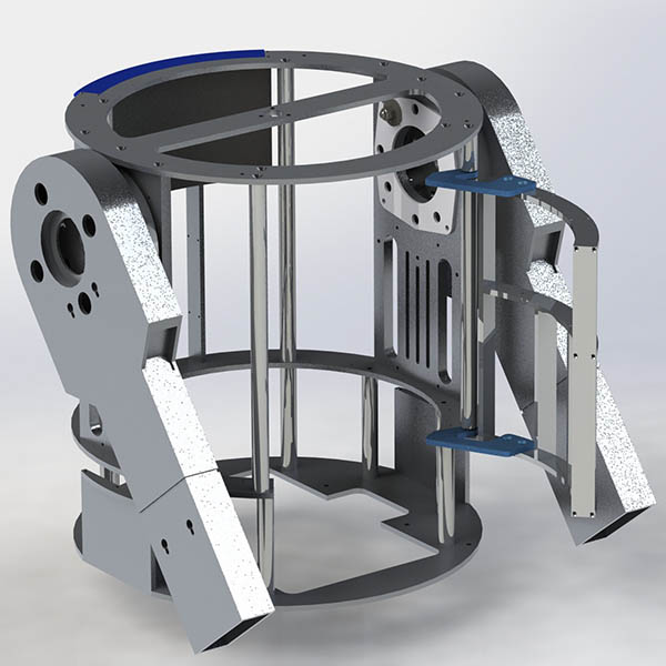
The first design of the hinged door. I'm trying to figure out where to put the retractable spring plunger I imagine will keep the door in place.
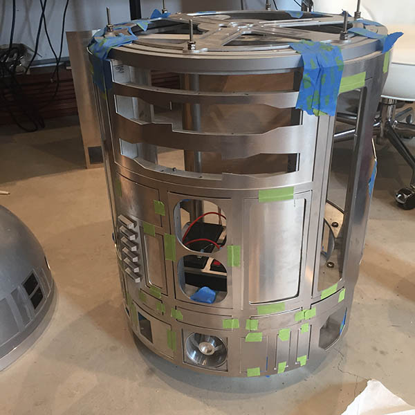
With the skins taped on
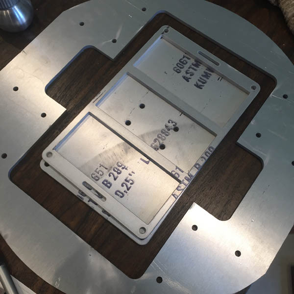
Installed skin mounting blocks to see how everything fit and yeah, the smaller diameter on the CSL frame leaves a tiny gap on the back-side. I've already raised the frame to fit the CSR skins but I'm going to make new medium riser rods anyway.
Legs and Shoulders
Despite my original idea to craft the legs myself (I even took welding classes you know) I decided to purchase a pair of legs from Wayne Orr. Purchasing a metal lathe is still on my list and so is getting a CNC mill but since I haven't pulled the trigger on those items yet I feel buying parts is okay to keep the project moving forward.
What I'm missing now is the Booster Covers. Also noticed that the one slot for the Shoulder Buttons on the Shoulder Horseshoe aren't slanted like in the original JAG drawings. I'm guessing noone will notice and I will have to check the reference droid at Lucasfilm next time I'm there.
So here are some pictures of the Legs and the Shoulders. It's coming along nicely and installing the components were very straight forward. Wayne was kind enough to supply all the hardware needed. If Anna sees another box from McMaster she's gonna think I have a screw obsession.
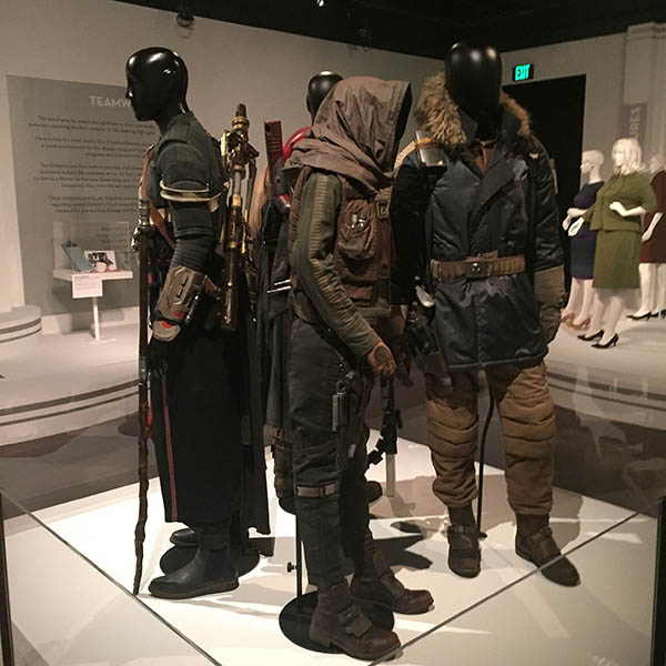
Last Saturday I went to the FIDM museum with Isabelle and they had a couple of costumes from Rogue One. Pretty cool.
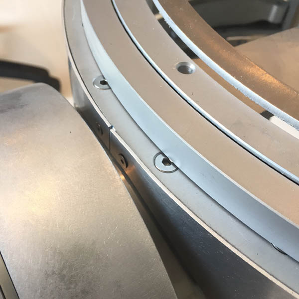
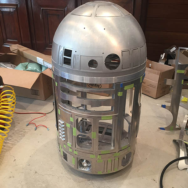
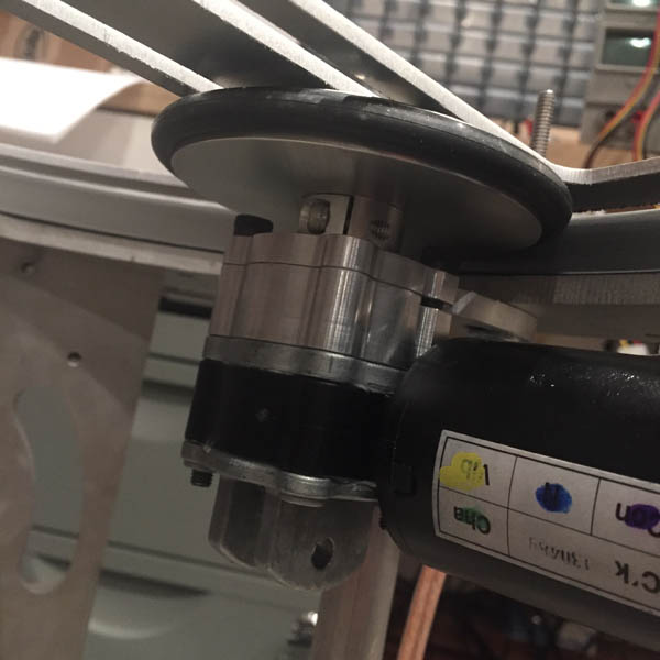
Dome Drive
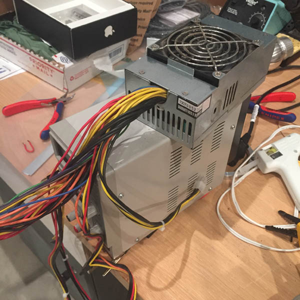
So after what I thought was a minor setback (I actually wrote a whole post about the failure before I realized what was wrong (after also having a monologue with Werner)), I managed to get my dome turning a little bit. My tiny little DC supply wasn't powerful enough to fully power the motor so I only got a slow rotation. At first I didn't get any movement at all and I thought it was a failure attributed to a stuck hex bit. It wasn't. So I butchered an old PC power supply and powered the motor.
And it spins! Yay! The dome drive is from Darren Murrer and it was easy to assemble and install.
I have also been working on a custom PSI light mount intended to be water jetted to fit, however my 3D prints worked very well so I don't think I need to make those parts in aluminum yet. At least I know it'll fit.
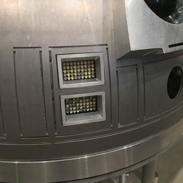
I've also put in some of the electronics in the dome but the LEDs in the small logic display are way too bright so I need to adjust that.
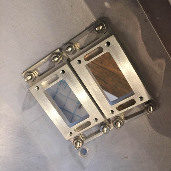
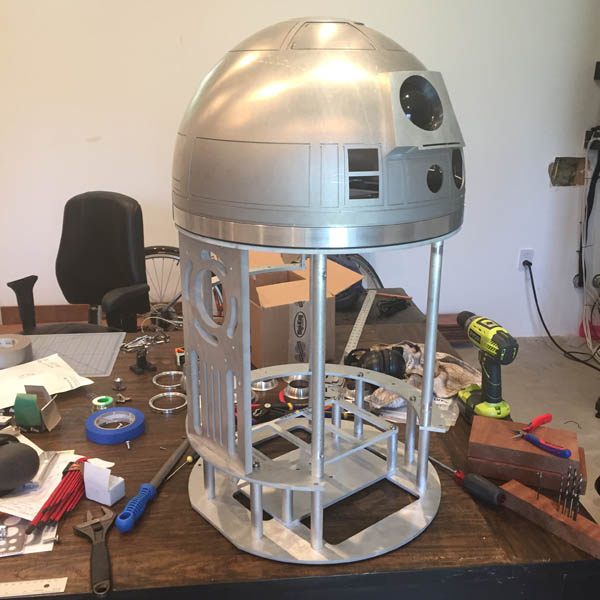
Holo Projectors
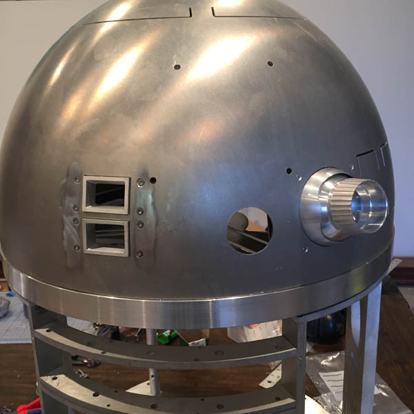
I mounted the holo projectors today too. It was way easier than I thought it would be. Looks great. Next step is epoxy and sanding things down. After that I'm ready to start assembling the dome, cut out the panels and send them off to the paint shop. I thought about painting things myself but I wanted a professional automotive expert coat the dome. I haven't fully decided yet. I might do it myself. What's the worst that could happen?
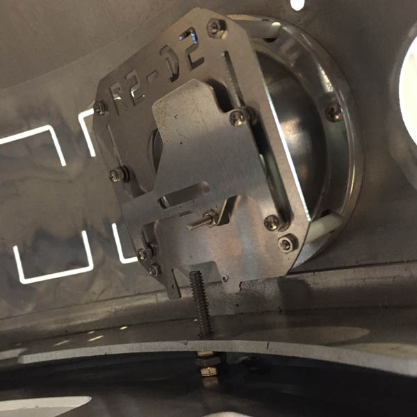
Logic Surrounds
The logic surrounds arrived the other day. They line up perfectly with the holes in the dome and they match the laser cut bezels I have printed. I might go for an aluminum/abs plastic instead of the 3D printed plastic. It might be sturdier.
Anyway. I mounted them on the inner dome. Will sand down the bolts and epoxy them to fix them in their position. When putting the outher dome on, you have to remove all the little thingies for it to fit.
By using epoxy on the bolt heads I'm hoping that I can reposition everything without having access to the heads.
Oh, I broke another tap. So bloody annoying. I'm starting to suspect that the hole I drilled was too small. Anyway, I have another job scheduled for more parts so I might as well make some backup rails.
Rods and Frame
Finally got my rods from the shop. I wanted them cut to the exact length and I don't have the tools to do it at my house. I also brought my shoulder plate to the guy hoping that he would be able to remove the broken tap. He couldn't and he has probably seen more broken taps than most. It's really stuck in there.
So instead I took it over to Charisma and Ron said he was going to try and water jet it out. Like hit it a few times with the jet, hoping to break it. So next time you're tapping something, remember to lube up - otherwise the heat will weld the fragments with the hole and the tap and it'll get stuck. Lesson learned.
Next issue. Since the frame I built is based the CSL drawings from JAG I didn't fully account for the discrepancy between the two different skins. So, the spacing between the holes on the sides are about an inch off. So, the Skin Mounting Blocks have to be made a bit different. The bottom one will have to be mounted under the second assembly ring instead of against the Shoulder Plate. Not a big deal, just some more Solidworksing to design the part. But that's for when I get back from Sweden.
More drilling and tapping
When I got the frame parts they had most holes already cut out. Obviously the holes on the sides weren't there so I had to drill those which was a bit of a challenge since the compound vice I have didn't fit the drill press. So I had to come up with a mounting plate to mate the two.
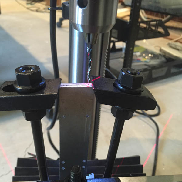
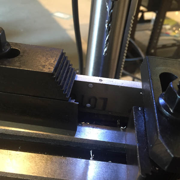
Drilling the holes went fine. Everything lined up the way I wanted it to. Once challange was the horizontal rail (it's curved) and you have to drill perpendicular to the mounting surface. With some wooden blocks clamped to the side drilling went fine.
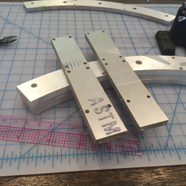
Here we go. I just realized I'm missing the #4-40 machine screws for the rails. McMaster to the rescue. Good thing they have a warehouse here in LA.
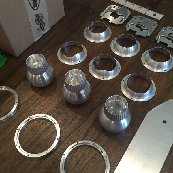
Here are Bob C's hololights. They are absolutely amazing and I'm thankful he did a run. These would have been kinda tricky to make on my own without a lathe. The hololights on the original droid were modified aircraft overhead vents. These are probably a lot sturdier than the originals.
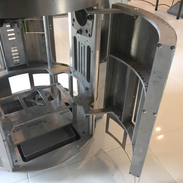
Assembled parts of the frame
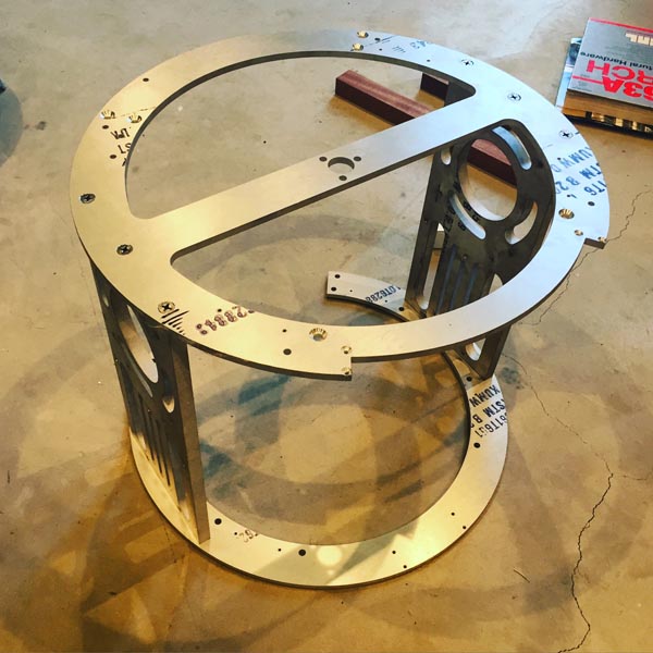
The Shoulder Plates are almost finished. I just had to assemble it to see it standing there. My tap wrench was too big for my #10-32 tap so I couldn't tap all the smaller holes. And of course I broke the 1/4-20 tap in the last hole. So annoying. Well, now I will learn how to remove a broken tap.
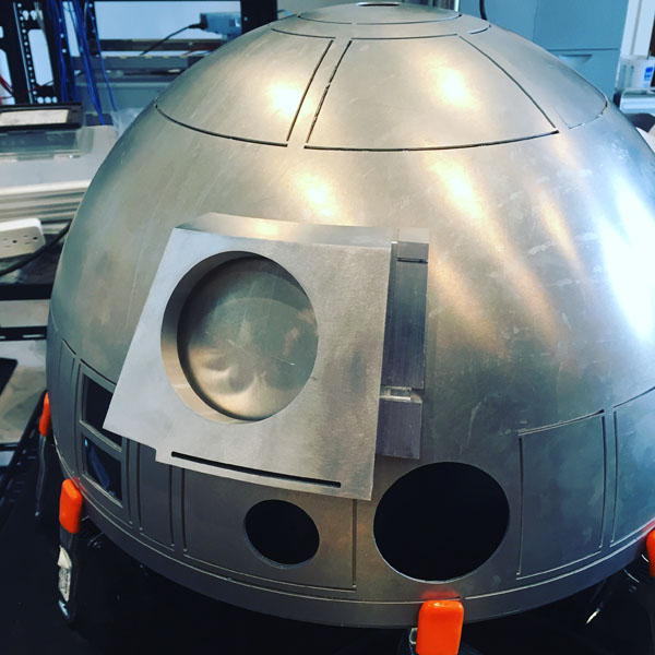
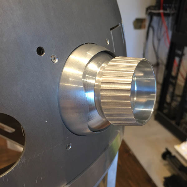
Here's the dome from Darren Murrer with the Radar Eye piece mounted.
I've got the Holo Lights in a box here and will start mounting them as soon as time permits. I'm also designing a set of hinges with servo mounts for the dome. I'll have the same company that did my frame parts cut them out.
Starting to document the build
For a few years now I've been thinking about builing an R2D2. There are many ways to go about it and many options for materials. After lurking on the astromech.net site for some time, studying the available drawings and reading other people's blogs I decided to pull the trigger.
I decided to build the droid completely out of aluminum. I knew I didn't want to just buy parts from other builders and for me, this was as much of a learning excersize as anything. I begun the project by mocking up all the parts in Solidworks and making sure everthing lined up. There are several versions of the drawings and I decided to go primarily with CSR (Club Specification Revised) which is based on measurements from the Lucasfilm archives. The CSL (Club Specification Legacy) was the drawings the R2 Builder's club published in early 2000.
While I sucessfully drew all the parts there were some parts I felt was a bit over my head or would be prohibitively expensive to make on my own. For example the dome and the holo lights were sourced from other members of the club. I also found a builder here in LA that had CSR skins to sell.
The first parts that I made were the frame. I drew up a modified version of the JAG frame. I found a company locally that could waterjet them for me.
If you'thinking about building a droid you'll quickly find that mcmaster.com and digikey.com are website you'll go to frequently and spend way too much money. If you live in Los Angeles, you'll probably take a few trips to Industrial Metal Supply too.
So, I expect this project to be finished sometime 2018 if I'm lucky. With a baby and other work comitments I can' really work fulltime on this project. But it's a nice hobby.